This post is part 1 of the "Enigma Cipher Chip" series:
- Part 1 - An Enigma I Cipher Machine on Skywater 130nm Via TinyTapeout
- Part 2 - Version 1 of the Enigma in Amaranth HDL
- Part 3 - Final Version of the Enigma in Amaranth HDL

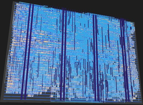
My final GDS for the Enigma machine (source available on github)
I stumbled across TinyTapeout offering very low cost chip shuttles last month, and decided I had to get on their next shuttle in March 2025. For the early-bird pricing of US $150, you can design and tapeout a (small) 160umx100um digital circuit on Skywater 130nm, fabricated right here in the USA. You only get one chip and a test/bring-up PCB at that price, but what a deal for getting actual custom silicon in your hands!
TinyTapeout (TT) is a non-profit promoting educational chip design, and are sponsored by eFabless who run their own commercial shuttle programs. TT are on their 10th shuttle (with fabricated chips from TT06 currently shipping to customers). They use a fully open-source flow OpenLane2, to compile schematics (see their cool educational GUI Wokwi) or RTL into GDS in a matter of minutes. There's no complicated setup and they've done such a superb job at simplifying chip design that you can literally submit your source to a github repo and have a commit hook run the flow and generate working/verified GDS in a matter of minutes. They had over 300 designs in TT09, and not only was every one of those open-source, but even cooler, you received a chip with access to all the designs to test if you liked.
1 My submission to TT10
I've always wanted to really understand exactly how a World War II era German Enigma cipher machine worked. So, I thought building a circuit version in RTL would be the perfect way to learn this, and additionally test out an open source synthesis and place and route flow. It proved quite challenging to fit all the logic required into 0.016 \(\mu m^2\) but you can see my complete submission source and overview on github. I used Amaranth HDL for the first time, which is a Python based HDL, to generate the verilog for this project.
I'll try to explain my design in more detail below, with a brief background on how the Enigma machines worked.
2 Enigma background
There are many great articles on the web [1] [2] about the Enigma machine, so I won't go into much detail here. At its heart, it's a substitution cipher machine using principles going back to Caeser's time (and probably earlier), where each input character is substituted with a different character according to a fixed pattern. For example, in the Enigma, one of the mechanisms used the following substitution pattern for letters A-Z: EKMFLGDQVZNTOWYHXUSPAIBRCJ. So, for example, an input 'A' would yield 'E' the first time through.
2.1 Rotors
One mechanism to do a substitution was a physical wheel, or Rotor, that had 26 contact points on each side as shown in the figure.
Enigma Rotor
An electrical current would be applied on one side at the first of the 26 contact points, denoting the input character 'A'. The rotor has internal wiring that then connects to the 5th contact on the other side, denoting an 'E'.
By itself, this would be an easy cipher to crack just by using letter frequencies, but the key innovation in the Enigma machine was that before each letter, the fixed pattern would be shifted by one by rotating the rotor one place. Thus, the fixed pattern for the next character then becomes: KMFLGDQVZNTOWYHXUSPAIBRCJE. Therefore, if you input another 'A', it would be encrypted into 'K' this time, instead of an 'E'.
Each original Enigma machine had 3 slots for 3 different Rotors (user selectable) that the electrical current could flow through right-to-left. Each Rotor could not only apply its own substitution to the incoming letter, but it could also rotate independently of the other Rotors. I've shown a high-level block diagram of such an arrangement below, but mapped the 26 one-hot signals for each letter into a 5-bit binary representation. Thus, each Rotor takes a 5-bit number (in reality <26) and outputs a different 5-bit number.
3 Enigma Rotors connected right to left
2.1.1 Rotor rotation
Each Rotor type [5] had a fixed notch location; for example, for the Type I discussed above, the notch location was at "Q". This notch was used to rotate the adjacent Rotor, similar to how digits in an old-school car odometer used to work.
- The first Rotor (leftmost) would rotate before every input letter.
- Once the first Rotor goes past its turnover (notch) letter, the second (middle) Rotor would rotate once
- Similarily, once the second Rotor went past its turnover point, it would trigger a rotation of the third Rotor.
One important idiosyncracy of the mechanical design of the Rotor design was the double step of the middle rotor [6]. After the turnover of the first Rotor, if the second Rotor has rotated to its turnover point, on the very next letter the second and third Rotor would rotate once. This means, effectively, the second Rotor has rotated twice in a row (double-step).
2.2 Reflector
Another unique feature of the Enigma was the use of a reflector at the left-most side that applied its own substitution before reflecting the signal back out to the right. The reflector did not rotate, so it always applied its fixed substitution pattern. Once reflected, the signal then made itself back through the three rotors before exiting, going through 7 substitutions so far.
Reflector plus three rotors
This reflection makes the Enigma symmetric allowing it to decrypt and encrypt with the same settings.
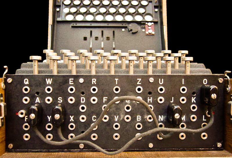
2.3 Plugboard

Photograph of plugboard [4]
The wartime Enigmas, beginning with the Enigma I had one other feature for doing substitution, which was a board with 26 connection points. The operator would use patch cables (up to 13, but standardized later to 10) to connect two letters together. This patch cable implemented a swap of the two letters. It turns out that if you do the math [3], this conceptually straightforward addition greatly increased the encryption strength of the Enigma machine from under a billion configurations to over \(2^{76}\) or 107,458,687,327,251,000,000,000 configurations for the standard Enigma 1.
Complete encryption/decryption path
Now that we have all the components of the Enigma, let's take a look at how I implemented them in RTL in part 2 of this series.
3 References
| [1] | https://www.cryptomuseum.com/crypto/enigma/working.htm |
| [2] | https://www.ciphermachinesandcryptology.com/en/enigmatech.htm |
| [3] | https://www.nsa.gov/portals/75/documents/about/cryptologic-heritage/historical-figures-publications/publications/wwii/CryptoMathEnigma_Miller.pdf |
| [4] | https://commons.wikimedia.org/wiki/File:Enigma-plugboard.jpg |
| [5] | https://en.wikipedia.org/wiki/Enigma_rotor_details |
| [6] | https://www.youtube.com/watch?v=hcVhQeZ5gI4 |