This post is part 2 of the "Enigma Cipher Chip" series:
- Part 1 - An Enigma I Cipher Machine on Skywater 130nm Via TinyTapeout
- Part 2 - Version 1 of the Enigma in Amaranth HDL
- Part 3 - Final Version of the Enigma in Amaranth HDL
1 Enigma Implementation
The first part of this series described the background of the Enigma Cipher Machine with the following datapath:
Complete encryption/decryption path
In this post, I'll take a quick dive into how I implemented a simple version of it using Amaranth HDL. While there is a finite-state-machine to generate the control signals, we'll defer discussion of that until the next article.. Most of the deeper implementation details will be found in that post.
2 Version 1 - Combinational datapath
My initial design modeled the Enigma shown in the figure above as a combinational datapath. The 5-bit input character flows through each block (plugboard, three rotors, reflector, three rotors, and back through the plugboard) and comes out transformed into the final encrypted 5-bit value.
2.1 V1 Plugboard
I designed the plugboard as a lookup table. The 5-bit input character indexes into a 26-row x 5-bit memory, and the contents of the row is the character it should map to. For a completely unconnected plugboard, a row lookup returns its address: e.g. the letter "E" would address row 4, which would contain the value 4 which corresponds to letter "E" again. On the other hand, if a plug is connected between E and A, then the following entries are present in the table:
Plugboard using 1W/2R Register File
- lookup[4] = 0
- lookup[0] = 4
This lookup table was implemented as a register-file with one synchronous write port (to "load" the plug settings), and two asynchronous (combinational) read ports. We need two read ports in V1 because the forward (left-to-right) and backward (right-to-left) path need separate lookups.
The code for this can be found here.
2.2 V1 Rotor
The Rotor is also effectively a lookup table, except the entries are fixed per Rotor type, so we don't need a writable register-file/memory. In addition, there are a few settings we need to track per Rotor, to model how an operator could adjust it in an Enigma machine:
- Each rotor type has a fixed turnover point where it "overflows" and triggers a rotation in the rotor to the left.
- Each rotor could be inserted into the machine and rotated to a given "start" letter. (start_ptr)
- The current rotation count (5-bit counter) (cnt)
- In addition, each rotor had a ring setting (ring_setting set at initialization) that allowed the right side with the wiring pattern to be rotated (offset) from the left side contacts.

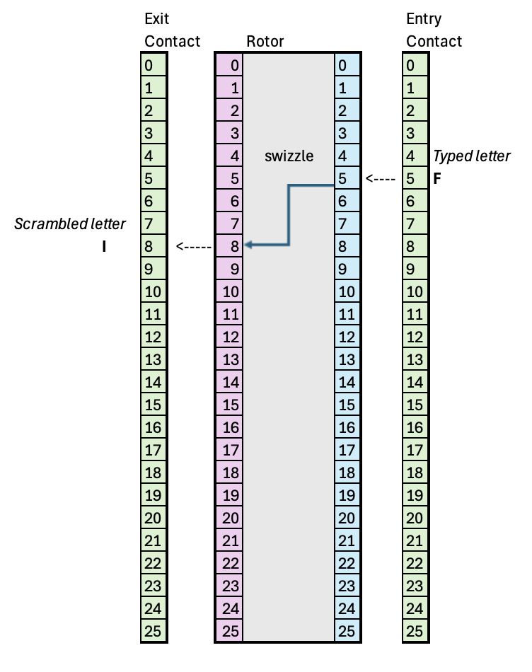
Rotor plus absolute contact points on entry (right side) and exit (left side) in default position (start_prt=0, cnt=0, ring_setting=0). An input letter "F" would be scrambled to "I".
The first thing to do is adjust for the start position, which is simply adjusting cnt at initialization:
cnt = start_ptr
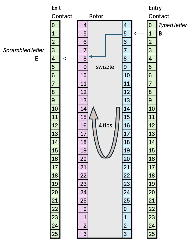
Then, on every input letter, we need to do is calculate which input on the rotor wiring pattern is contacted by the incoming letter. Because the ring has rotated by cnt tics, we need to add that offset to the incoming letter position:
contact_point = (input_char + cnt) % 26

Rotor has rotated four tics, and now, an input letter "B" would be scrambled to "E", using the same wire connection in the previous figure
Now, we can use the Rotor lookup table to calculate which position on the rotor's left side it exits at:
exit_point = rotor_swizzle[contact_point]
Now, this exit_point is with respect to the rotor wheel, but because that has rotated by cnt tics, we need to subtract that out to get the absolute position the signal exits at:
result = exit_point - cnt
2.2.1 Adjusting for ring setting
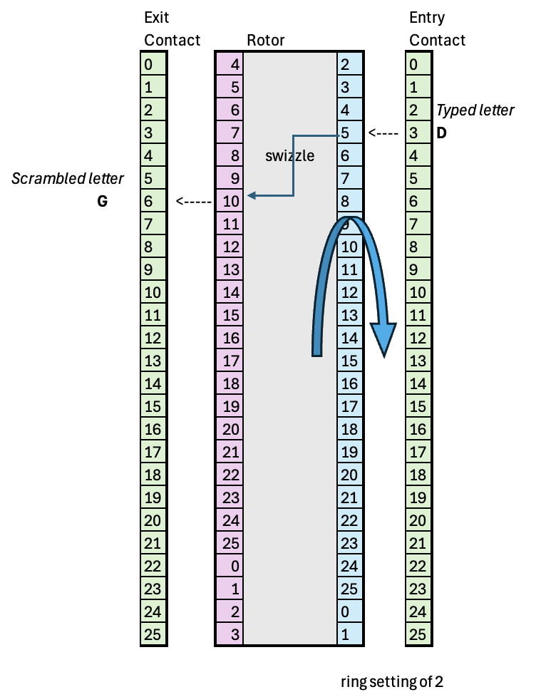
Now, the ring setting needs to be accounted for. Because the ring setting only rotates the right side of the rotor, sliding the whole wiring pattern clockwise with respect to the left side of the rotor, we end up with a new contact point on the right side. We can model this by taking the start position and subtracting out the ring setting. Thus, the top-most contact point on the rotor on the right side in the figure below becomes \(4 - 2 = 2\), which is where an incoming "A" would contact.
cnt_ring_combined = (cnt - ring_setting) % 26
contact_point     = (input_char + cnt_ring_combined) % 26

# Rest is the same
exit_point = rotor_swizzle[contact_point]
result = (exit_point - cnt_ring_combined) % 26

Rotor has rotated four tics, and now, has an additional ring setting of 2, such that an input letter "D" would be scrambled to "G", using the same wire connection in the previous figure
2.2.2 The complete Amaranth HDL for the rotor
First, let's take care of the imports:
from amaranth import *
from amaranth.lib import wiring
from amaranth.lib.wiring import In, Out
Before we jump into the actual Rotor class, the subclasses that specify each Rotor type will be represented as follows:
class Rotor_I(Rotor):
    _wiring = 'EKMFLGDQVZNTOWYHXUSPAIBRCJ'
    _turnover = 'Q'
class Rotor_II(Rotor):
    _wiring = 'AJDKSIRUXBLHWTMCQGZNPYFVOE'
    _turnover = 'E'
class Rotor_III(Rotor):
    _wiring = 'BDFHJLCPRTXVZNYEIWGAKMUSQO'
    _turnover = 'V'
Notice how we can use straightforward strings to specify each Rotor, unlike in Verilog. We will convert these ASCII values into 5-bit integers (0 to 25) at RTL elaboration time below.
Next, let's look at a Rotor base-class component in Amaranth with a separate right-to-left and left-to-right combinational path for scrambling. It has control inputs that will enable it, rotate it once, or load the start and ring settings.
It will also generate a flag is_at_turnover to signal if the next character should turnover the adjacent Rotor.
class Rotor (wiring.Component):

    # Right to left path
    right_in: In(5)
    left_out: Out(5)

    # Left to right path
    left_in: In(5)
    right_out: Out(5)

    is_at_turnover: Out(1)

    # Control signals
    en: In(1)
    load_start: In(1)
    load_ring: In(1)
    inc: In(1)
We also need to setup some control signals to allow loading of the internal state variables to keep track of the start and ring settings. These will be loaded from the right_in bus if the Rotor is enabled (en asserted) and the respective load_* signal is asserted. The right_in bus will also be passed through to left_out when any of these load signals are asserted, to allow adjacent Rotors to also be loaded in sequence via its en signal.
Next, let's define some state variables.
def __init__(self):
    self.wiring = self._wiring     # Wiring patter for each Rotor subclass
    self.cnt = Signal(5)           # Current position of rotor
    self.right_ptr = Signal(5)     # Comb. pointer into wiring table for right-to-left path
                                   # based on right_in, cnt, and ring_setting
    self.rtol_swizzle = Signal(5)  # Comb. output value for right-to-left
    self.ring_setting = Signal(5)  # Stored ring setting
    self.turnover = Const(ord(self._turnover)-65)  # Constant letter for turnover from subclass

    self.left_ptr = Signal(5)      # Comb. pointer into wiring table for left-to-right path
    super().__init__()
Finally, let's go into the implementation, or elaboration
def elaborate(self, platform):
    m = Module()

    with m.If(self.en):
        with m.If(self.load_start):
            m.d.sync += self.cnt.eq(self.right_in)
        with m.Elif(self.load_ring):
            m.d.sync += self.ring_setting.eq(self.right_in)
        with m.Elif(self.inc):
            m.d.sync += self.cnt.eq((self.cnt+1) % 26)

    # Convert ASCII definition to 0-25 range for the right-to-left swizzle
    mapping = [ord(c)-65 for c in self.wiring]
    # Convert ASCII definition to 0-25 range for the left-to-right swizzle
    mapping_ltor = [0]*26
    for i, c in enumerate(self.wiring):
        mapping_ltor[ord(c)-65] = i

    # Generate a runtime indexable table in Amaranth for each mapping (swizzle) using an Array construct
    Wiring = Array(mapping) # right_to_left mapping
    Wiring_left_to_right = Array(mapping_ltor)

    # Calculate turnover
    m.d.comb += self.is_at_turnover.eq(self.cnt == self.turnover)

    # Convert absolute entry (right_in) to relative contact point on
    # the rotor by adding its rotation (cnt) while subtracting out the ring_setting
    m.d.comb += self.right_ptr.eq((self.cnt + self.right_in - self.ring_setting ) %26)

    m.d.comb += self.rtol_swizzle.eq(Wiring[self.right_ptr])

    # Need a mux on the left_out bus to pass through right_in when loading Rotor settings
    m.d.comb += self.left_out.eq(
        Mux( self.load_start | self.load_ring,
            self.right_in,
            (self.rtol_swizzle-self.cnt + self.ring_setting)%26))

    # Left to right
    m.d.comb += self.left_ptr.eq((self.cnt + self.left_in - self.ring_setting) % 26)
    m.d.comb += self.right_out.eq((Wiring_left_to_right[self.left_ptr] - self.cnt + self.ring_setting) % 26)

    return m
2.3 Version 1 Issues
While the combinational datapath had no problems meeting timing up to 10MHz or so, a more serious issue was exceeding the area budget even with fixed Rotor types.
2.3.1 Plugboard area
The plugboard register-file synthesized into a D-flip-flops(DFFs), consuming a large amount of area. I made the decision to go to D-latches in the next version, which have much smaller area. With latches, the write pulse needs to be handled carefully to ensure the write data stays stable well past the write enable falling edge. Fortunately, since we don't really have any performance constraints, a control state machine can be used to sequence this across multiple cycles.
2.3.2 Rotor area
The Rotor area increased significantly because of the modulus operator used everywhere for adding/subtracting to the rotor pointer. I realized that the mod is unnecessary, since I just need specific add or subtract operations that wrap around at 25 and 0 respectively. I could implement custom RTL to do this and reduce the area.
The next article in this series. will explore the optimized version